|
|
vlrPhone and vlrFilter |
The VLC and VLR Codecs for the Beamforming Microphone Arrays
Generalities
From Wikipedia:
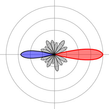
- Beamforming or spatial filtering is a signal processing technique used in sensor arrays for directional signal transmission or reception. This is achieved by combining elements in a phased array in such a way that signals at particular angles experience constructive interference while others experience destructive interference.
- To change the directionality of the array when transmitting, a beamformer controls the phase and relative amplitude of the signal at each transmitter, in order to create a pattern of constructive and destructive interference in the wavefront.
Beamforming - Wikipedia
Beamforming can be used for radio or sound waves.
Main areas of use:
- Radar.
- Sonar.
- Seismology.
- Wireless Communications.
- Radio Astronomy.
- Acoustics.
- Biomedicine.
Algorithms for the beamforming microphone arrays
There are two categories of algorithms used for the beamforming microphone arrays:
1) Conventional or Fixed Beamformers.
One can cite:
- Delay-and-Sum Beamforming.
A conventional beamformer can be a simple beamformer also known as delay-and-sum beamformer. All the weights of the microphone elements can have equal magnitudes. The beamformer is steered to a specified direction only by selecting appropriate phases for each microphone.
The delay-and-sum beamformer is the oldest and simplest type of beamformer.
It is a data independent beamformer and its response remains fixed at all times. It is simple to implement, it has no negative effect, but it requires a large array of microphones for a decent directionality.
- Filter-and-Sum Beamforming.
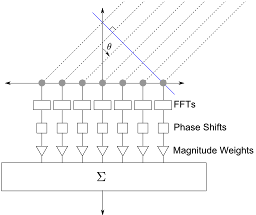
The filter-and-sum beamforming is one of the simplest beamforming techniques but still gives a very good performance. It is based on the fact that applying different phase weights to the input channels the main lobe of the directivity pattern can be steered to a desired location, where the acoustic input comes from. It differs from the simpler delay-and-sum beamformer in that an independent amplitude weight is applied to each of the channels before summing them.
Both the amplitude and phase weights can be frequency dependent.
2) Adaptive Beamformers.
An adaptive beamformer is a system that performs adaptive spatial signal processing with an array of transmitters or receivers.
One can cite:
- MVDR, or Minimum Variance Distortionless Response, or Capon Beamformer.
The MVDR beamformer is capable of determining the weight vectors for beam steering.
It uses the filter-and-sum beamforming and the frequency domain.
- LCMV, or Linearly Constrained Minimum Variance, or Frost Beamformer.
Each microphone is filtered by a FIR filter with M coefficients.
It can be considered as the equivalent of the MVDR beamformer in the time domain.
- Griffiths-Jim Beamformer.
This technique combines a standard fixed beamformer (delay-and-sum) with an adaptive filtering.
The VLC and VLR Audio Codecs (audio compression and decompression methods)
In the general case, these codecs use the greatest points (foreground), the most energetic bands (background), the magnitudes and the phases, and a 50% or less frame overlapping.
For the background, one can use only the magnitudes and the sign of the phases.
The bands of the background, taken separately, can be encoded in parallel.
If you take all the points of the background or contiguous bands only, there is no need to compute the energy of the bands or to select the most energetic bands.
You can get a very high quality by increasing the accuracy of the magnitudes and phases, especially for the points of the foreground.
These codecs can be used for all the sampling rates, are based on FFT only and are very fast.
It should be noticed that these codecs being based on FFT, they can be further accelerated with the graphics processing support (GPU, Graphics Processing Unit) and can include a very important number of simultaneous channels.
Listening Page
The VLC and VLR Codecs for the data from the beamforming microphone arrays
These codecs can efficiently encode data from the beamforming microphone arrays, with or without pre-processing on the transmitter side (compression), and with the possibility of rapid processing on the receiver side (decompression).
The quality of the desired result (noise reduction, spatial filtering, ...) depends on the number of microphones and the most efficient algorithms use FFT.
In addition to allow efficient compression, the two-plane decomposition can also allow a more efficient application of the beamforming algorithms in the frequency domain.
Noting that most of the moderate noises are in the background (See Noise Reduction):
- For the foreground, constructive interference can be applied.
- For the background, destructive interference can be applied.
- The foreground alone can be steered to a specific direction. The computations are faster because the most FFT bins are identically null for all the microphones.
The VLC and VLR codecs with irregular beamforming microphone arrays
- Virtually all the theories on the beamforming microphone arrays concern microphones spaced in a regular manner, for example in a line, in a plane or on a sphere. Also, many of these theories are not applicable in real time.
Beamforming microphone arrays with irregular arrangements may be much more efficient, but to date, there are few studies to take them into account.
- With the vlrFilter project (see below), it will be possible to take into account these configurations, empirically, by varying the magnitudes and the phases thanks to sensors (accelerometer and gyroscope) integrated in a radio remote control, and using buttons on the remote control.
These sensors will also be able to control the orientations in 3D.
- With the vlrFilter project, it will not only be possible to listen to audio signals, but also physiological signals (thanks to the sonification), in 3D or by privileging a listening direction.
- A simple formula will be applied for each FFT bin (foreground) of each input channel.
To each channel i will be associated an angle theta_i (azimuth) and an angle phi_i (elevation).
The magnitudes will be modulated according to the following formula:
Mag_i (theta, phi) = Mag0_i * cos (theta-theta_i) * sin (phi-phi_i + PI / 2)
In this formula:
- cos and sin denote the cosine and the sinus.
- theta and phi are the angles given by the sensors.
- Mag0_i is the maximum magnitude for channel i, and can also be modulated using the buttons on the remote control or a configuration file.
The phases will be modulated by buttons on the remote control.
- For the in-line or in-plane arrangements, on can activate only one angle (theta).
The magnitudes will then be modulated according to the following formula:
Mag_i (theta) = Mag0_i * cos (theta-theta_i)
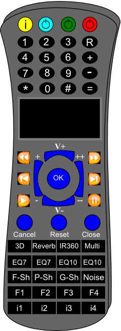
Radio remote control, with accelerometer and gyroscope, for the vlrFilter project.
- Red button: for standby.
- Green button: to take into account a non-audio signal (physiological signals for example).
- Cyan button: to activate the sensors (accelerometer and gyroscope).

Radio USB receiver
vlrFilter Project
From Wikipedia:
- Beamforming or spatial filtering is a signal processing technique used in sensor arrays for directional signal transmission or reception. This is achieved by combining elements in a phased array in such a way that signals at particular angles experience constructive interference while others experience destructive interference.
- To change the directionality of the array when transmitting, a beamformer controls the phase and relative amplitude of the signal at each transmitter, in order to create a pattern of constructive and destructive interference in the wavefront.
Beamforming - Wikipedia
Beamforming can be used for radio or sound waves.
Main areas of use:
- Radar.
- Sonar.
- Seismology.
- Wireless Communications.
- Radio Astronomy.
- Acoustics.
- Biomedicine.
Algorithms for the beamforming microphone arrays
There are two categories of algorithms used for the beamforming microphone arrays:
1) Conventional or Fixed Beamformers.
One can cite:
- Delay-and-Sum Beamforming.
A conventional beamformer can be a simple beamformer also known as delay-and-sum beamformer. All the weights of the microphone elements can have equal magnitudes. The beamformer is steered to a specified direction only by selecting appropriate phases for each microphone.
The delay-and-sum beamformer is the oldest and simplest type of beamformer.
It is a data independent beamformer and its response remains fixed at all times. It is simple to implement, it has no negative effect, but it requires a large array of microphones for a decent directionality.
- Filter-and-Sum Beamforming.
The filter-and-sum beamforming is one of the simplest beamforming techniques but still gives a very good performance. It is based on the fact that applying different phase weights to the input channels the main lobe of the directivity pattern can be steered to a desired location, where the acoustic input comes from. It differs from the simpler delay-and-sum beamformer in that an independent amplitude weight is applied to each of the channels before summing them.
Both the amplitude and phase weights can be frequency dependent.
2) Adaptive Beamformers.
An adaptive beamformer is a system that performs adaptive spatial signal processing with an array of transmitters or receivers.
One can cite:
- MVDR, or Minimum Variance Distortionless Response, or Capon Beamformer.
The MVDR beamformer is capable of determining the weight vectors for beam steering.
It uses the filter-and-sum beamforming and the frequency domain.
- LCMV, or Linearly Constrained Minimum Variance, or Frost Beamformer.
Each microphone is filtered by a FIR filter with M coefficients.
It can be considered as the equivalent of the MVDR beamformer in the time domain.
- Griffiths-Jim Beamformer.
This technique combines a standard fixed beamformer (delay-and-sum) with an adaptive filtering.
The VLC and VLR Audio Codecs (audio compression and decompression methods)
In the general case, these codecs use the greatest points (foreground), the most energetic bands (background), the magnitudes and the phases, and a 50% or less frame overlapping.
For the background, one can use only the magnitudes and the sign of the phases.
The bands of the background, taken separately, can be encoded in parallel.
If you take all the points of the background or contiguous bands only, there is no need to compute the energy of the bands or to select the most energetic bands.
You can get a very high quality by increasing the accuracy of the magnitudes and phases, especially for the points of the foreground.
These codecs can be used for all the sampling rates, are based on FFT only and are very fast.
It should be noticed that these codecs being based on FFT, they can be further accelerated with the graphics processing support (GPU, Graphics Processing Unit) and can include a very important number of simultaneous channels.
Listening Page
The VLC and VLR Codecs for the data from the beamforming microphone arrays
These codecs can efficiently encode data from the beamforming microphone arrays, with or without pre-processing on the transmitter side (compression), and with the possibility of rapid processing on the receiver side (decompression).
The quality of the desired result (noise reduction, spatial filtering, ...) depends on the number of microphones and the most efficient algorithms use FFT.
In addition to allow efficient compression, the two-plane decomposition can also allow a more efficient application of the beamforming algorithms in the frequency domain.
Noting that most of the moderate noises are in the background (See Noise Reduction):
- For the foreground, constructive interference can be applied.
- For the background, destructive interference can be applied.
- The foreground alone can be steered to a specific direction. The computations are faster because the most FFT bins are identically null for all the microphones.
The VLC and VLR codecs with irregular beamforming microphone arrays
- Virtually all the theories on the beamforming microphone arrays concern microphones spaced in a regular manner, for example in a line, in a plane or on a sphere. Also, many of these theories are not applicable in real time.
Beamforming microphone arrays with irregular arrangements may be much more efficient, but to date, there are few studies to take them into account.
- With the vlrFilter project (see below), it will be possible to take into account these configurations, empirically, by varying the magnitudes and the phases thanks to sensors (accelerometer and gyroscope) integrated in a radio remote control, and using buttons on the remote control.
These sensors will also be able to control the orientations in 3D.
- With the vlrFilter project, it will not only be possible to listen to audio signals, but also physiological signals (thanks to the sonification), in 3D or by privileging a listening direction.
- A simple formula will be applied for each FFT bin (foreground) of each input channel.
To each channel i will be associated an angle theta_i (azimuth) and an angle phi_i (elevation).
The magnitudes will be modulated according to the following formula:
Mag_i (theta, phi) = Mag0_i * cos (theta-theta_i) * sin (phi-phi_i + PI / 2)
In this formula:
- cos and sin denote the cosine and the sinus.
- theta and phi are the angles given by the sensors.
- Mag0_i is the maximum magnitude for channel i, and can also be modulated using the buttons on the remote control or a configuration file.
The phases will be modulated by buttons on the remote control.
- For the in-line or in-plane arrangements, on can activate only one angle (theta).
The magnitudes will then be modulated according to the following formula:
Mag_i (theta) = Mag0_i * cos (theta-theta_i)
Radio remote control, with accelerometer and gyroscope, for the vlrFilter project.
- Red button: for standby.
- Green button: to take into account a non-audio signal (physiological signals for example).
- Cyan button: to activate the sensors (accelerometer and gyroscope).
Radio USB receiver
vlrFilter Project
|
|
|
|
|
|